
Features
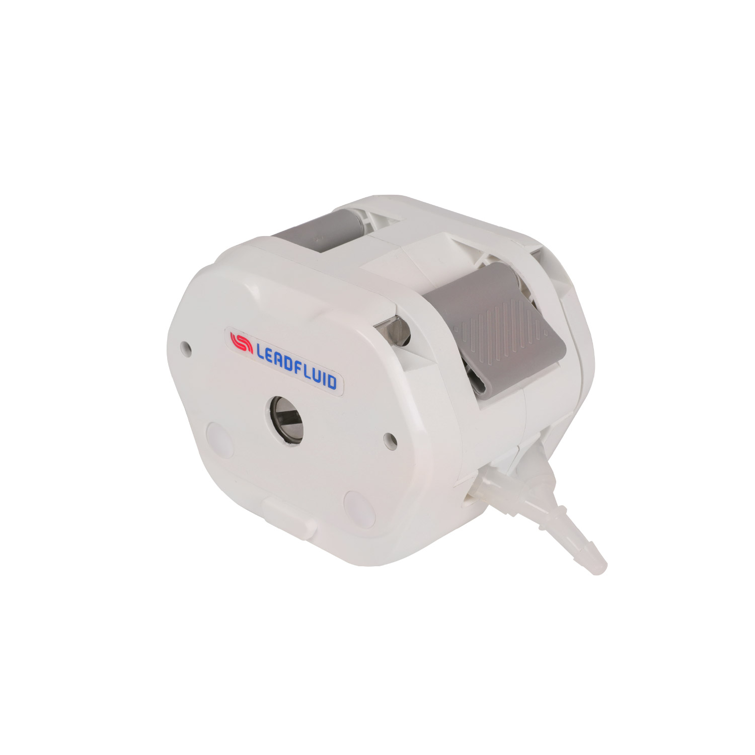
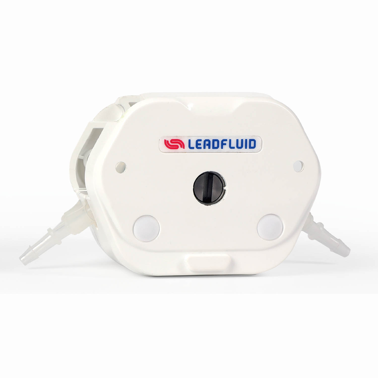
• Convenient Tube Loading Design
Equipped with dedicated fittings, eliminating the need for special tube clamps. The tube is automatically centered, simplifying the tube loading process and improving work efficiency.
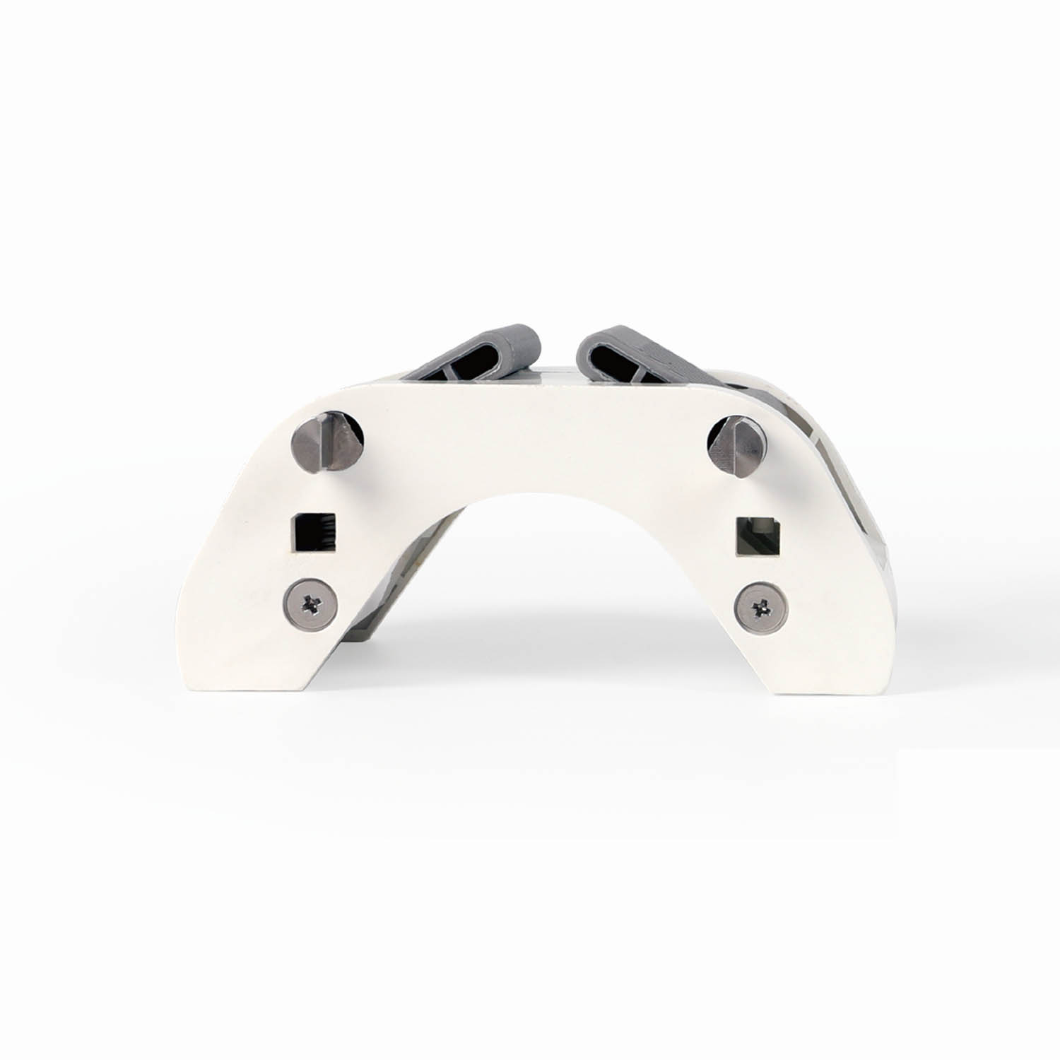
• Elastic Pressure Block, Versatile Compatibility
The elastic pressure block design effectively reduces the risk of leakage, enhances stability, and extends tube life. It is compatible with various tube sizes, meeting diverse requirements.
• Comfortable Operating Experience
The anti-slip textured dual-ear lever allows for single-handed operation, providing a firm grip and a comfortable feel during use.
• Low Pulsation Control Technology
The roller phase compensation technology effectively reduces pulsation, enhancing filling accuracy and stability.
• Enhanced Safety Features
Supports the optional automatic shutdown function when the cover is opened, improving operational safety.
Technical Parameter
Applicable tube: 13#,14#,19#,16#,25#
Max speed: ≤600rpm/min
Max flow rate: ≤2070mL/min
Transfer pressure: 0.12Mpa
Channel: 1
Roller: 3
Cascading: No
Material: Pump head shell-Reinforced Nylon; Rollers-304 Stainless Steel
Working environment: Temperature 0 ~ 40℃, relative humidity<80%
Tube compression structure: Elastic Pressure Block
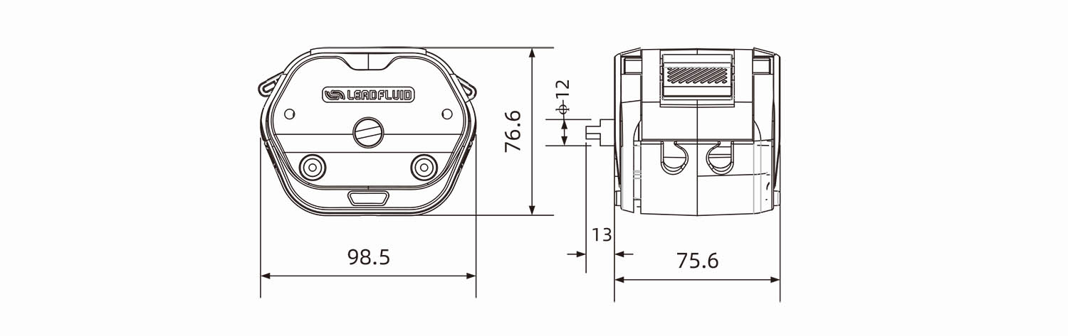
Dimensions(L*W*H): 98.5×76.6×75.6 mm
Pump head weight: 0.55kg
Optional functions: Cover-open pump stop
Tube Selection
| Material | Model | Length | Remark |
| Silicone tube | 13#14#19#16#25# | 129mm | Excludes tube connector |
• DMD15 applicable tube kits are listed in Table 1.
• The wall thickness and inner diameter precision of the hose can impact the flow accuracy.
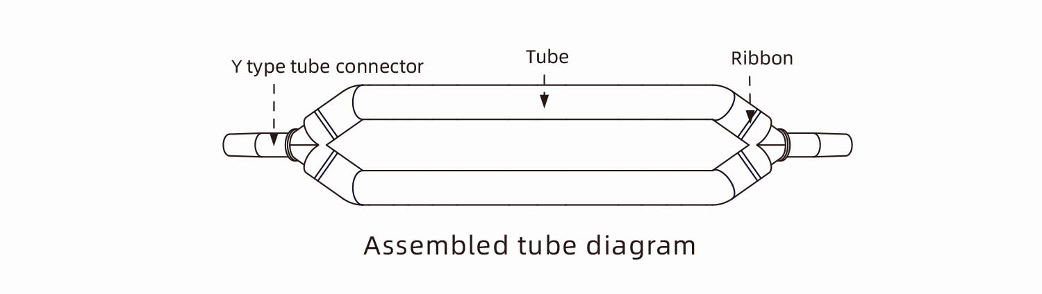
Table 1
Tube Installation
1.To remove the upper clamp assembly: Rotate both clamp levers upward (left lever clockwise, right lever counterclockwise), then firmly grip the assembly and lift vertically to detach.
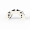
2.Place the tube kit in the roller and the tube slots on the left and right sides. Secure the Y type three-way connector at both ends of the tube kit in the slots, ensuring the tube is straightened to prevent it from being crushed.
3-4. Attach the upper pressure block: After placing the upper pressure block, pull down the left and right levers (rotate the left lever counterclockwise and the right lever.
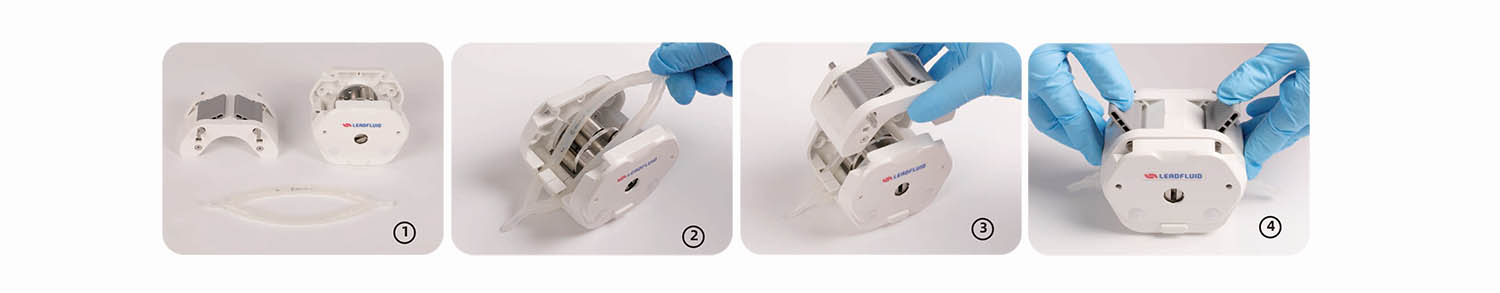
Tube Installation Diagram
DMD15 Series Pump Head Flow Rate Parameter
| Model | Speed(rpm) | Tube | ||||
| DMD15 | Dual 13# | Dual 14# | Dual 19# | Dual 16# | Dual 25# | |
| 0.1 | 0.01 | 0.04 | 0.09 | 0.17 | 0.3 | |
| 1 | 0.1 | 0.4 | 0.9 | 1.7 | 3 | |
| 30 | 3 | 14 | 28 | 52 | 106 | |
| 50 | 5 | 23 | 50 | 88 | 180 | |
| 100 | 11 | 48 | 101 | 175 | 365 | |
| 150 | 16 | 74 | 152 | 265 | 542 | |
| 350 | 39 | 166 | 354 | 613 | 1266 | |
| 600 | 66 | 280 | 590 | 1030 | 2070 | |
Above flow parameters are obtained by using silicone tube to transfer pure water under normal temperature and pressure,in actually using it is effected by specific factors such as pressure, medium etc. Above for reference only.
Dimension(mm)
Application fields:
Pharmaceuticals, Chemicals, Food and Beverage, Laboratories, and More.
Typical applications:
Drug Filling, Precise Proportioning of Chemical Raw Materials, etc.