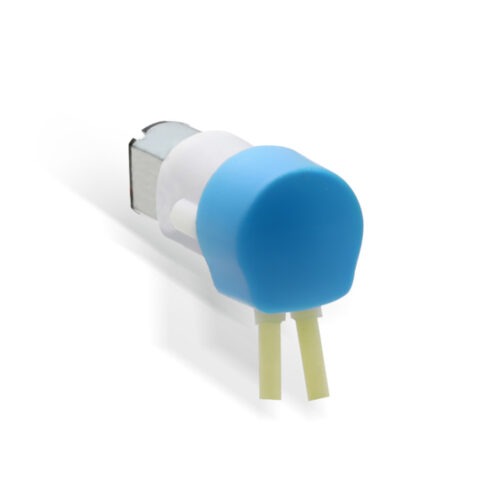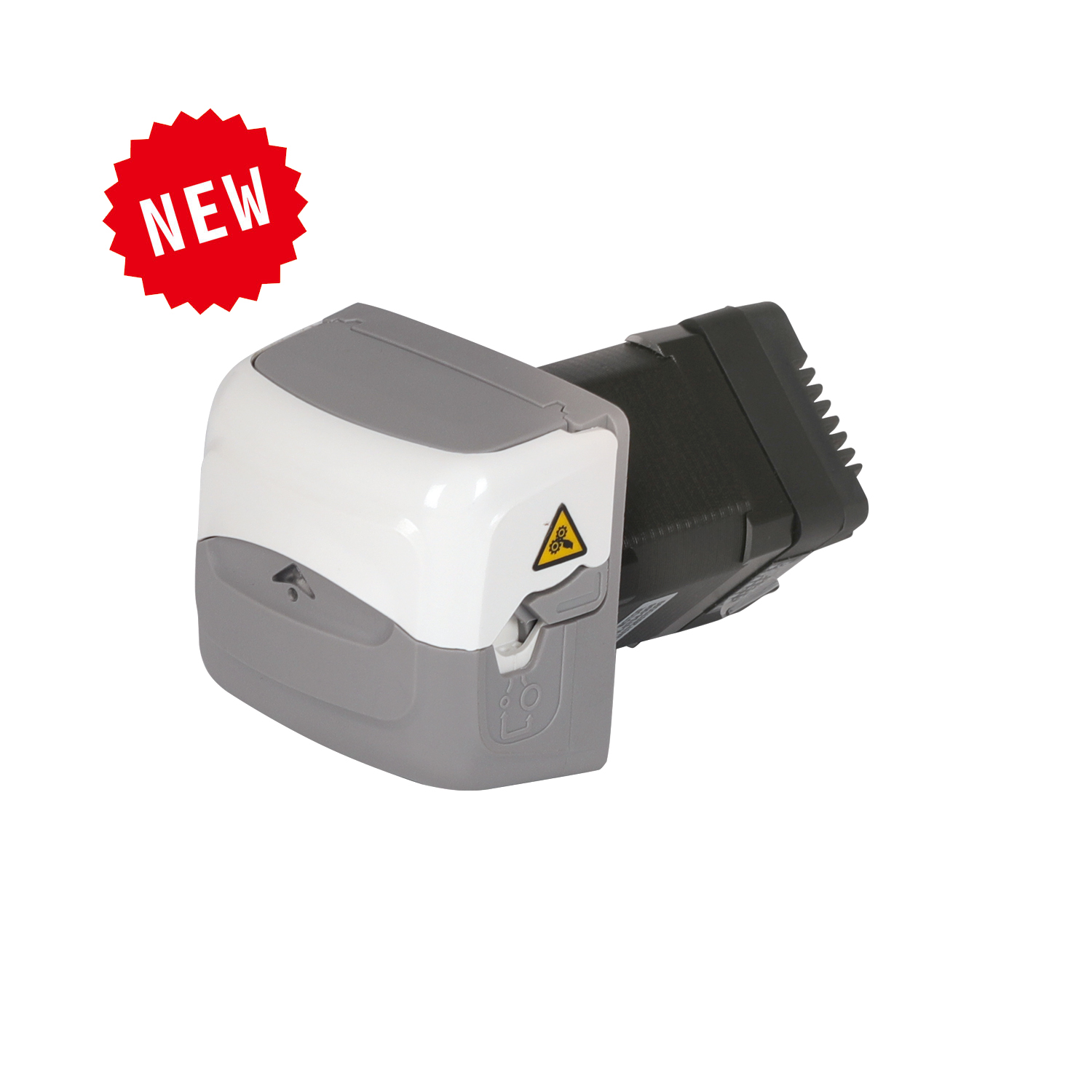
Peristaltic Pump Introduction
• The product has an attractive appearance and a compact design.
• Pulse stability.
• The tube installation process is simple, and it prevents the tube from automatically stretching after installation.
• It features a configurable setup with two adjustable pressure modes: standard pressure and high pressure.
• Driven by a stepper motor, the pump head requires no special maintenance.
• The control method is analog control (K1/K2/K3 correspond to 4–20 mA / 0–5 V / 0–10 V).
Application
• Attractive appearance, compact size, and suitable for installation in space-limited areas.
• Precise volumetric and flow-rate transfer, focused on low-flow applications.
• Easy to integrate in OEM setups.
Function and Features
• The drive motor is directly connected to the pump head, making installation and use very convenient.
• The enclosure is made of modified nylon; the rollers are made of PET.
• With high corrosion resistance, the performance is reliable.
• Flip cover design, easy to use and quick, saves operating space,
• Easy and convenient tube replacement; the self-adaptive tube clamp can accommodate various tubing sizes.
• Pressure levels can be adjusted according to requirements to suit different operating needs.
• The clamp’s position can be adjusted and switched to fit various tube specifications, ensuring it meets different installation needs.
Pump Parameters
Motor Types: 42 stepper motor
Control and Drive Methods: DC12-24V
Power: 20W
Control Mode: Analog input (K1/K2/K3 correspond to 4–20 mA / 0–5 V / 0–10 V)
Start-Stop Method: External level signal control (DC 5–24 V)
Direction Switch Method: External level signal control (DC 5–24 V)
Speed Range: ≤400rpm
Max flow Rate: ≤370mL/min(Silicone tube)
Channel Number: 1 channel
Roller Number: 4 rollers
Running Direction: Clockwise/Counterclockwise rotation
Lift Height: 8 m
Suitable Tube Wall Thickness: 1.6 mm
Suitable Tube Specifications: 13#(0.8mm), 14#(1.6mm), 19#(2.4mm), 16#(3.2mm), 25#(4.8mm)
Tube Material: Silicone tube, Pharmed tube, A-60G
Tube Installation Method: Adaptive tube clamps
Types of Tube Pressure: Elastic gap
Material of Pump Head Shell: Enhancing Nylon
Material of Pump Head Roller: Roller: PET; Metal parts: 304
Noise: ≤ 60db (testing environment noise ≤40dB, horizontal distance between test product and noise meter is 1 meter)
Pump Head Weight: 470g (without tube)
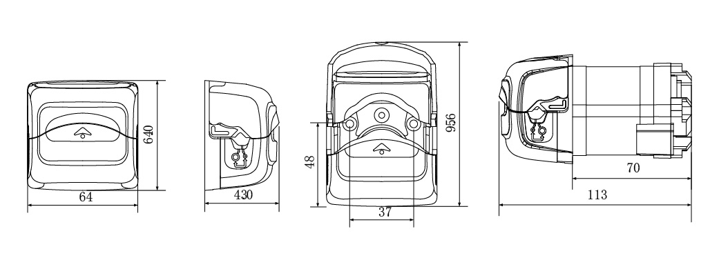
Dimensions: 64mm×64mm×113mm
Working Environment: Temperature 0- 40°C, , Relative humidity< 85% RH
Storage Environment: In a clean and well-ventilated environment with ambient temperatures ranging from -40 to +50°C,and relative humidity not exceeding 95%, the air must not contain corrosive, flammable gases, oil mist, or dust.
Applicable Tube Model and Flow Reference Table
| Tube Material | Tube No. | Flow Rate(mL/min) | |||||
| 1rpm | 30rpm | 60rpm | 100rpm | 200rpm | 400rpm | ||
| Pharmed | 13# | 0.04 | 1.2 | 2.5 | 4.1 | 8.3 | 16.5 |
| 14# | 0.14 | 4.2 | 8.5 | 14 | 28 | 57 | |
| 19# | 0.29 | 8.7 | 17.5 | 29 | 58 | 115 | |
| 16# | 0.5 | 15 | 30 | 50 | 100 | 200 | |
| 25# | 0.92 | 27 | 55 | 92 | 184 | 370 | |
• The above flow data were all tested using a Lead Fluid silicone tube to pump pure water under laboratory conditions with normal temperature and pressure. This data is for reference only. Due to pressure in actual use , temperature, medium characteristics, tube material and other specific factors, the specific situation needs to consult our engineers.
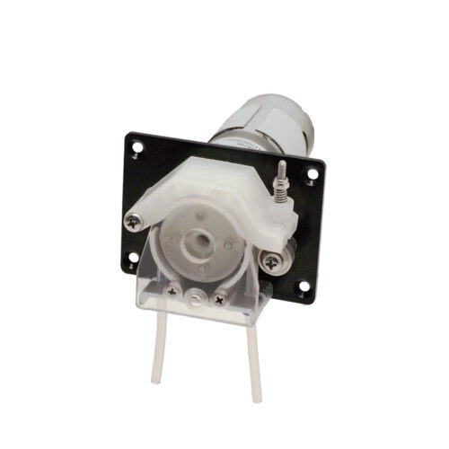
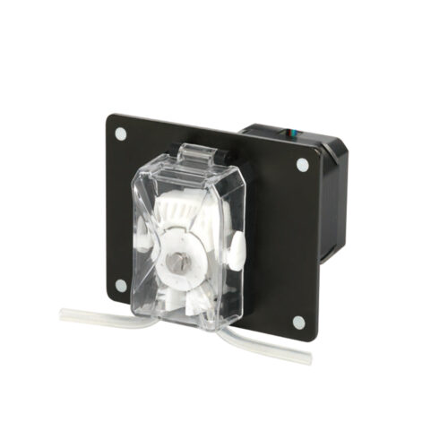
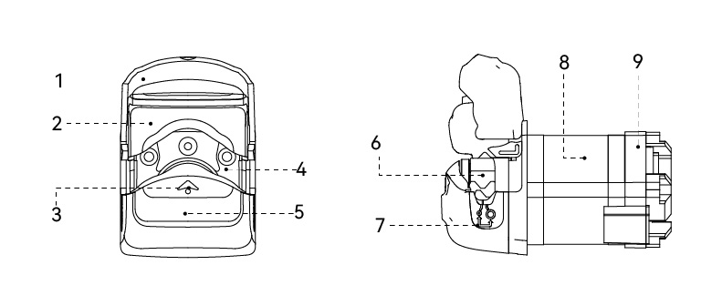
Head Pump Structure
Component name and function:
1. Active front cover: move the front cover to open/close the tube installation space of the pump head.
2. Upper pressure bracket: install the working pressure block.
3. Observation window: view the pump head operating state through the transparent window.
4. Main body: mounts the motor and provides installation positions for the complete unit.
5. Support: supports the pump head core.
6. Pump head core: the working component of the squeezed tube.
7. Position of tube clamp: Indicates the current position of the tube clamp;
8. Motors: Provide power.
9. Drive and control unit: controls the motor motion.
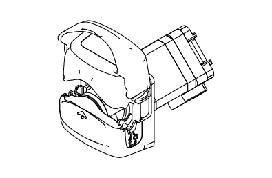
Usage Method
Step 1: Move the front cover to lift the upper pressure bracket and open the tube installation space.
Step 2: Place the tube into position, then move the front cover back. Reset the upper pressure bracket to complete tube installation.
Dimension Drawing of Exterior and Opening(mm)
Application Fields:
Biopharmaceuticals, Medical Equipment, Laboratory Instruments, and Various OEM Supply NeedsTypical
Applications:
Biochemical Fermentation, Dentistry, Surgical Irrigation, etc.